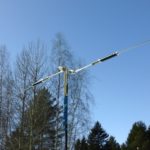
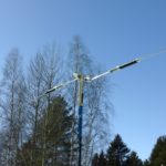
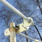
This weekend I’m working with the Super Antenna MP1DXMax. It is in a horizontal dipole configuration, similar to a Buddipole. If the weather holds, I’ll be using it to work some digital modes on HF. I also hope to get enough material to make a horizontal dipole tutorial for the MP1C. For now, this blog post will have to do.
As a man portable field operator, it’s important to find the best balance of performance and break down size when it comes to an antenna. That’s why I use the “compromise” antennas most often in the field. Magloops, short verticals, Endfeds, … Sometimes we should look at other alternatives to see if we can increase the performance of our compromised choices. For that, I’m looking at self-supporting dipoles. Since I already have two of the MP1C antennas, I’ll start here.
As it normally goes, what I thought was going to be a simple setup, turned into a learning experience. The fix was simple, and also something I would not have thought of. Thanks to Bonnie KQ6XA for getting me sorted.
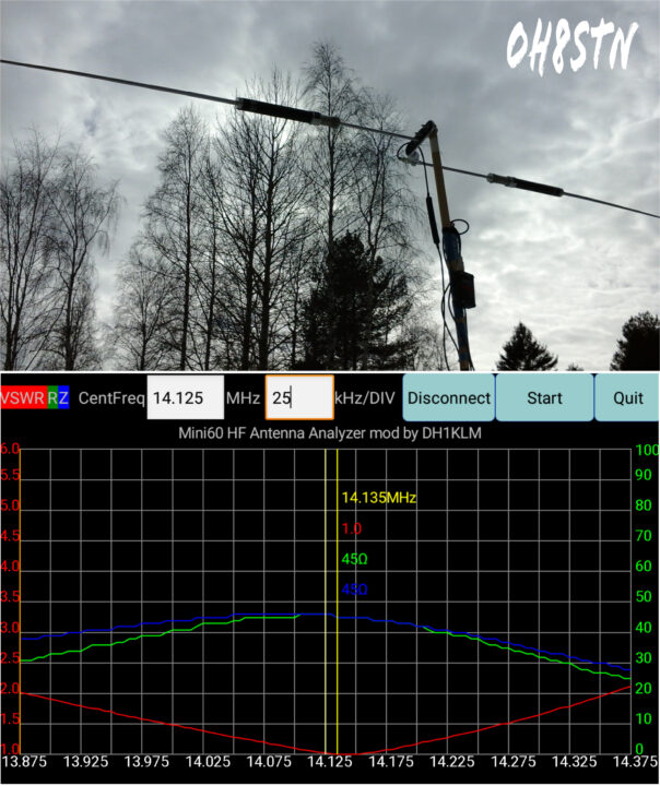
The setup is totally straight forward, yet I wasn’t able to initially get the SWR down below 3.5. We can ignore the issues I had for now, and I’ll document them later in this article.
Set-up
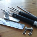
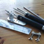
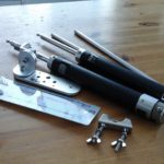
We are going to need:
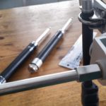
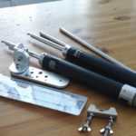
- 1x UM2 Universal Mount
- 2x MP1x antenna
- 2x Telecopic whips
- 2x extension rods
- 1 inch Schedule 80 pipe of equivalent.
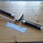
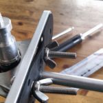
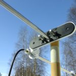
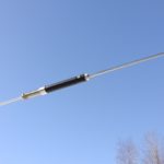
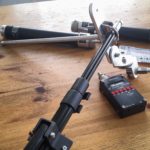
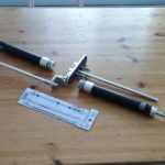
The hot side of the antenna is mounted to the SO239 to 3/8 x20 adapter. Insert an extension rod into that hole. The cold side is mounted in the 3/8 x 20 hole at the near center of the UM-2 Universal Mount. Insert the second extension rod into that hole. (Note: Make sure you insert the extenstion rod first before the u-bolt. The u-bolt will interfere with the proper seating of the extension, causing high SWR).
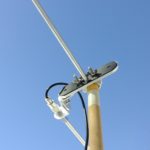
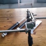
Now attach the u-bolt to the two center holes on the UM2. As I mentioned in the last paragraph, the u-bolt interferes with the extension. There are a couple of ways to deal with this. You can use a dremel to remove the material from the u-bolt backing, making room for the extension. Or you can do as I have, drilling out the second 1/4 tripod mount on the end of the UM2. This effectively moves the u-bolt out-of-the-way of the extension, yet leaves your primary 1/4 inch tripod mount intact. In the following images, you can see the before the mod, then after the mod.
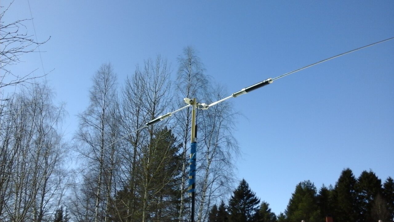
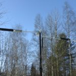
When you have the MP1x installed on either side of the UM2, you can install your telescopic whips. There is no need to extend them until the dipole will be raised.
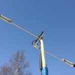
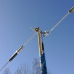
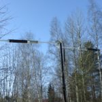
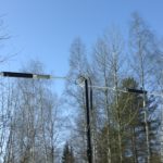
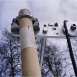
Mast Mounting
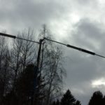
We use the schedule 80 pipe to affix the dipole to the mast-head. In my case the mast-head is a tripod. As you can see, I didn’t have any schedule 80 pipe, so I used a broomstick. The reason for this is to have a non-conductive mount for the dipole. Also insure the mast is far enough away from the dipole to prevent any coupling, which will also raise your SWR.
Tuning
The most difficult part of getting this dipole to work is understanding the cold side needs to be shorter than the hot side. This was the second part of my initial fail. The best way to understand it, is from the help and advice Bonnie KQ6XA shared about tuning.
From Bonnie
Sometimes the cold side needs to be offset a little lower in frequency than the hot side.
There’s lower band edge marks on some of the bands on the FG1 for this.
Set the cold side slider to the lower band edge.
Then set the hot side slider to the normal frequency mark.
Check with your analyzer, and then mark the opposite side of the FG1 with a sharpie marker.
Generally speaking, the height above ground and ground conductivity makes a lot of difference on how much the offset needs to be on each band.
It will be somewhat different in different soil conductivity or heights.
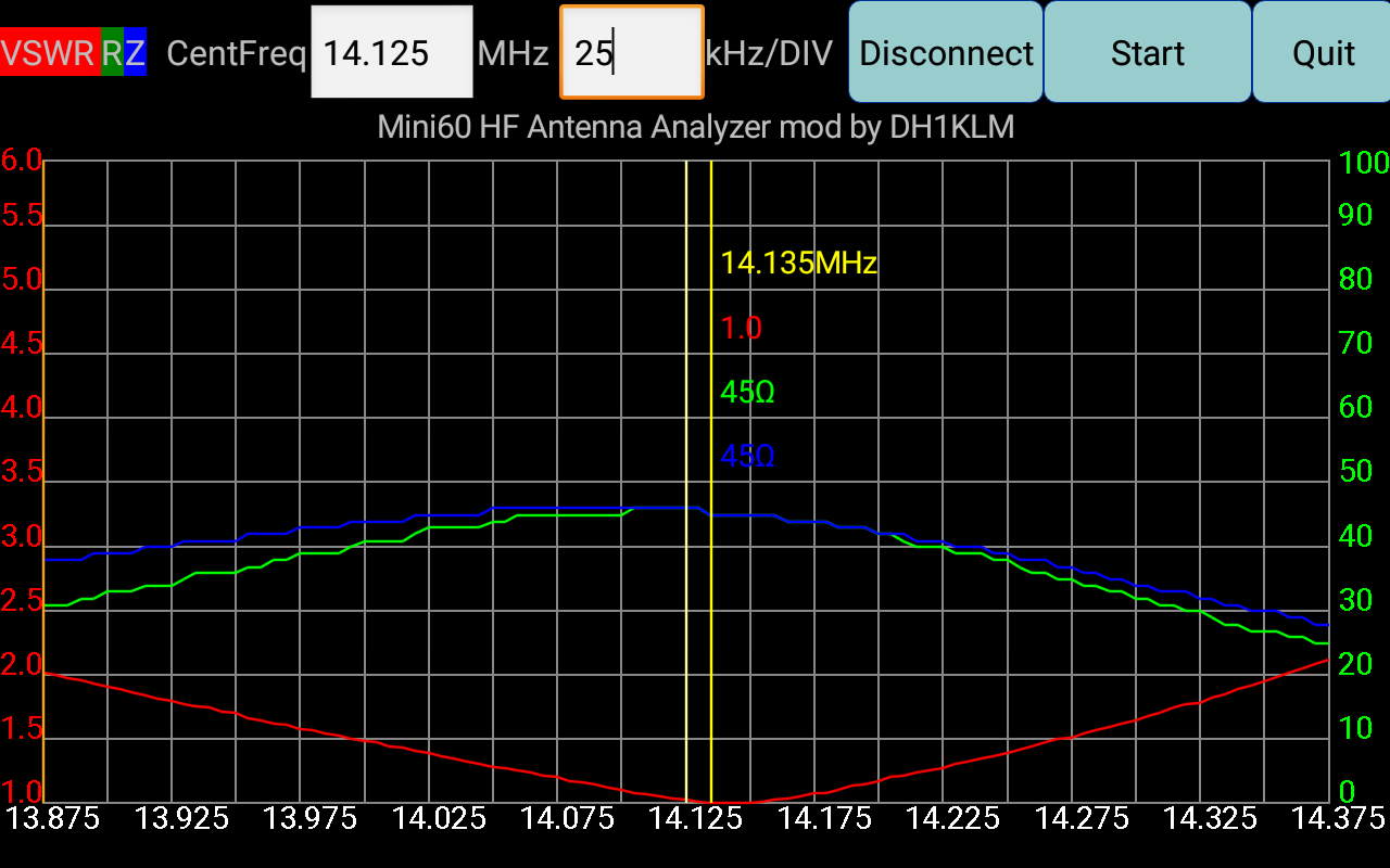
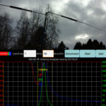
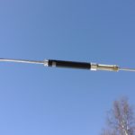
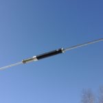
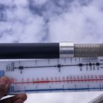
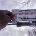
These next two images will show you the position of the hot and cold sides of the dipole using the FG-1 frequency guide. I found it easiest to tune the cold side like Bonnie suggested, then find lowest SWR using the hot side, repeat if necessary.
It should also be pointed out that bandwidth is much more narrow in this dipole configuration than a single vertical MP1C.
Let me know how this configuration works out for you.
de oh8stn
Below this section is the original article and troubleshooting
Troubleshooting
This section is from the original post. I’ve left it here to help anyone who find themselves in the same situation.
is from the original post. I’ve edited it to show the critical points with this setup. I’ve also added some tips from operators who read the original post and wanted to help.
In the end there were actually two problems.
- Tuning
- Universal Mount
This is what I have done so far.
- Tested SWR of each antenna across all HF bands individually. Both worked perfectly.
- Made certainly there was no continuity between center conductor and tip of connector with antennas connected. No continuity
- Checked continuity between all antenna elements and SO239 tip and ground (separately). Checked out
- Made certain each antenna were perfectly tuned on the same frequency as the other.
- Tried a dipole mount from another manufacturer, with identical results.
I have added images of the configuraton in hopes that someone might see something wrong in my configuration.
Any and all ideas will be helpful. At this point, I’ll keep troubleshooting. I also hope to learn from and gain the experience of others using similar configurations.
As usual, I’ll publish the (what I am sure will be a silly mistake) here, when It shows itself.
de oh8stn